
Контрактное производство электроники под ключ в Китае
Шэньчжэнь, район Баоань, улица Фуюн, улица Фуцяо, район 3, промышленный парк Лонгхуй 6

Will you encounter this situation when you are doing PCB design? There are white circles between the wire and the pad. It seems that there is nothing wrong with the drawing, but you just don't know what is wrong. Some people have to delete the line and redraw it to eliminate the error, or ignore the error altogether. So how to solve this problem? Next, Shenzhen PCB design company kingford for you to introduce.
The wrong solution:
Method 1: Press "T+M" key, disappear, visually comfortable. It will not affect the effect after PCB proofing.
Method 2: Click "DXP" -> "Parameter Selection" -> In PCB Editor, remove the check mark before Online DRC. It's better than the first one. In fact, both methods ignore errors, which is not true.
The right solution:
First, we run the design rule check in the toolbar and can see an error report. According to the error prompt, we can find the design rule in the toolbar.
In fact, it is the connection angle between the wire and the pad, check any angle (any Angle), you can fundamentally solve this error. Because the root of any error can be found in the rules. When you encounter an error, fix it, not ignore it!
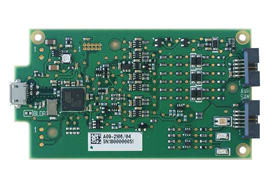
PCB can withstand 100A current PCB design method
Source: Technical article Responsible editor: Shenzhen Honglijie PCB Design Department
The usual PCB design current does not exceed 10A, even 5A. Especially in household, consumer electronics, usually the continuous working current on the PCB will not exceed 2 A. However, some products need the continuous current to reach about 80A. Considering the instantaneous current and leave a margin for the whole system, the continuous current of the power line should be able to withstand more than 100A. Next, Shenzhen PCB design company kingford introduces the PCB design method that can withstand 100A current.

2.PCB design method that can withstand 100A current
Method 1: Routing cables on the PCB
To understand the PCB overcurrent capability, we start from the PCB structure. Take a double-layer PCB, for example, which is usually a three-layer structure: copper, plate, copper. Copper is PCB current, signal to pass through the path. According to middle school physics knowledge can know an object's resistance and material, cross-sectional area, length. Because our current is going through the copper, the resistivity is fixed. The cross-sectional area can be seen as the thickness of the copper skin, which is the thickness of the copper in the PCB processing options. Copper thickness is usually expressed in OZ. 1OZ translates to 35um, 2OZ is 70um, and so on. It is easy to conclude, then, that in order to pass high currents on the PCB, the wiring should be short and thick, and the thicker the copper of the PCB, the better.
Actually in engineering, there is no strict standard for the length of wiring. In engineering, copper thickness/temperature rise/wire diameter are usually used to measure the current carrying capacity of PCB board.
A circuit board of 1 OZ copper is thick, and a 100 mil (2.5 mm) wide wire is capable of passing 4.5 A current at 10° temperature rise. In addition, with the increase of width, PCB current-carrying capacity does not increase strictly in line with the linear increase, but the increase range gradually decreases, which is also consistent with the actual project situation. If the temperature rise is increased, the current carrying capacity of the wire can also be improved.
Through the above summary, the PCB wiring experience can be obtained: increasing copper thickness, widening wire diameter and improving PCB heat dissipation can enhance the current carrying capacity of PCB.
So if I want to run 100 A current, I can choose 4 OZ copper thickness, set the wire width to 15 mm, double sided wire, and add heat dissipation device, reduce the temperature rise of PCB, improve the stability.
Method 2: Terminals
In addition to routing cables on the PCB, you can also route cables by using terminals.
Fix several terminals that can withstand 100 A on the PCB or the product housing, such as sticker nuts, PCB terminals, copper posts, etc. Then the wire that can withstand 100 A is connected to the terminal post with wiring terminals such as copper nose. So that the large current can travel through the wire.
Method three: Custom copper bar
Even, it can be customized. It is a common practice in industry to use copper bars to carry high current. For example, transformers, server cabinets and other applications all use copper bars to carry high current.
Method 4: Special process
In addition, there are some special PCB processes, which may not be processed by domestic manufacturers. Infineon has A PCB, using 3 layers of copper layer design, the top and bottom layer is the signal wiring layer, the middle layer is the thickness of 1.5 mm copper layer, specially for the layout of power supply, this kind of PCB can easily achieve a small volume of over 100 A current.
Shenzhen kingford is a PCB design company specializing in layout design of electronic products, mainly engaged in multi-layer and high-density PCB design and circuit board design proofing business, skilled in using the market mainstream PCB design software, professional and efficient communication to ensure the progress of PCB design. Help you seize the market opportunity one step earlier!


Достаточно загрузить файлы Gerber, BOM и проектные документы, и команда KINGFORD предоставит полное предложение в течение 24 часов.