
Контрактное производство электроники под ключ в Китае
Шэньчжэнь, район Баоань, улица Фуюн, улица Фуцяо, район 3, промышленный парк Лонгхуй 6

The essence of rigid pliable board is to FPC as a PCB layer or two circuit layer, and then to the PCB rigid part of milling processing, only retain the flexible part.
What is a hard and soft board
The birth and development of FPC and PCB gave birth to the new product of the combination of soft and hard board. Therefore, the combination of soft and hard board, is the Flexible circuit board and hard circuit board, after pressing and other processes, according to the relevant process requirements combined together, the formation of a circuit board with FPC characteristics and PCB characteristics.
Advantages and disadvantages:
Advantages: The combination of soft and hard board has the characteristics of FPC and PCB at the same time, so it can be used in some products with special requirements, both flexible and rigid areas, to save the internal space of the product, reduce the volume of finished products, improve the product performance is of great help.
Disadvantages: the combination of soft and hard board production process is many, the production is difficult, the rate of good products is low, the material, manpower is more, therefore, the price is more expensive, the production cycle is longer.
1, rigid adagio is not cheap, why the use of rigid adagio?
In hardware design, cost is often not the key factor;
First, reliability: rigid adagio can solve the installation reliability problem of FPC.
Connecting through connectors in FPC brings installation cost, installation inconvenience, installation reliability problems, and easy to short circuit, fall off and other problems. In the design of a mass-shipped barrel machine of Hikvision, we can see the phenomenon of repairing welding between FPC and PCB after the installation of FPC. Rigid adagio solves the problem of reliability of FPC installation.
Second, comprehensive cost:
Rigid adagio, although the price per unit area is increased, but saves the cost of connector, at the same time reduces the installation time, reduces the repair rate, reduces the repair rate, improves the productivity and reliability. The use of products in mass shipments is often effective in reducing costs.
So the calculated cost:
Area of rigid pliable * unit price of rigid pliable - processing time cost - FPC loose repair cost * Loose probability - whether the management cost brought by fewer types of boards is greater than the original PCB area * unit price of PCB +FPC price + connector price

Third, effectively improve signal quality
Because the connection is not made through a connector, the wiring continuity is better and the signal integrity is better.
Traditional IPC uses FPCS and connectors to connect the Sensor board to the main control board.
Just adagio (soft and hard combined board) knowledge
The rigid flexible plate can be used to integrate the main control board and sensor board, which solves many problems and meets the structural design requirements of the barrel machine.
Just adagio (soft and hard combined board) knowledge
2, rigid adagio design points:
A. It is necessary to consider the bending radius of the flexible plate. Too small A bending radius will be easy to damage.
B, effectively reduce the total area, optimize the design to reduce the cost.
C. The structure of the three-dimensional space after installation needs to be considered.
D. It is necessary to consider the optimal design of the number of lines in the flexible part.
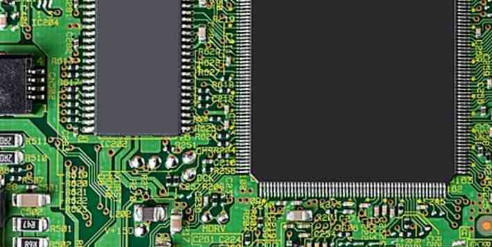
Pin sequence of electronic components on the circuit board
For most electronic components, they are polar or cannot be welded wrong. For example, electrolytic capacitors, once welded backwards, will explode when energized. Generally speaking, when using automatic feeding machinery to assemble circuit board components, there will be no problem of misplaced components. However, due to the limitations of the manufacturer and the characteristics of the components themselves, not all components can be automatically mounted or inserted.
Common manual placement of a variety of table attached transformers, connectors, TO package integrated circuits, etc. These devices are still subject to assembly errors. Generally, the repair is carried out manually. This link is also prone to reverse welding. Therefore, it is necessary to explain the positioning method of components and the corresponding relationship between component pad and screen printing on the circuit board.
1. Capacitance
For aluminum through hole installation of electrolytic capacitors, generally through the length of the foot and the mark on the body to indicate the positive and negative electrode. The long foot is positive and the short foot is negative. There are usually white or other stripes parallel to the pins on the negative side of the housing.
One way is to put a "+" sign directly on the positive side. The advantage of this method is that it is convenient to check the polarity after the welding is completed. The disadvantage is that the area of the circuit board is larger. The second method is to use silk screen to fill the negative terminal area. This polarity representation occupies a small area of the circuit board, but it is not convenient to check the polarity after welding. It is commonly used in the occasions where the density of circuit board devices is large, such as the computer motherboard.
Tantalum capacitors installed through holes are generally marked with "+" on the body of the positive electrode side, and some varieties are further distinguished by short and short feet. The marking method of this capacitor on the circuit board can refer to the aluminum electrolytic capacitor. For the surface of the aluminum electrolytic capacitor, the ink coated side is negative, positive side base is generally cut Angle treatment. It is generally printed on the circuit board with a "+" sign to indicate the positive terminal, while the outline of the device is drawn. So the side with the cut Angle can also be used to identify the positive terminal. For the sticker tantalum capacitor, it is generally three capacitors on the circuit board, the left side is negative, the right side is positive. The middle one is the most vivid.
FPC material properties
2023-03-30


Достаточно загрузить файлы Gerber, BOM и проектные документы, и команда KINGFORD предоставит полное предложение в течение 24 часов.