
Контрактное производство электроники под ключ в Китае
Шэньчжэнь, район Баоань, улица Фуюн, улица Фуцяо, район 3, промышленный парк Лонгхуй 6

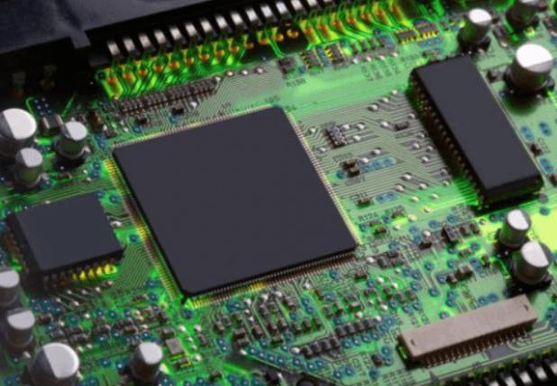
BGA welding generally refers to the welding of printed circuit boards. As people have higher and higher requirements on the function of electronic products and smaller and smaller volume requirements, in order to meet this need, the ball array packaging technology, namely BGA, has emerged. BGA welding, to put it simply, is a piece of circuit board attached with BGA components, through reflow welding process. When the BGA is repaired, the BGA is also manually welded, disassembled and welded by the BGA repair table and other tools.
For the welding of BGA, we use BGA Rework Station for welding. The tin balls on the BGA are classified as lead-free and leaded. The melting point of tin ball with lead is 183℃ ~ 220℃, and the melting point of tin ball without lead is 235℃ ~ 245℃.
According to the temperature curve, BGA welding can be roughly divided into four sections: preheating zone, insulation zone, reflux zone and cooling zone.
1. Preheating zone
Also called ramp zone, used to raise the PCB board temperature from the ambient temperature to the required active temperature. In this zone, the circuit board and components have different heat capacities and their actual temperature rise rates are different. The temperature of the circuit board and components should not exceed 2 ℃ to 5℃ per second. If the temperature is too fast, there will be thermal shock, and the circuit board and components may be damaged, such as subtle cracks in the ceramic capacitor. The temperature rise is too slow, welding paste will feel excessive temperature, insufficient solvent volatilization, affect the quality of welding. The preheating zone of the furnace generally accounts for 15 ~ 25 % of the whole length of the heating zone.
2. Insulation area
Sometimes called the dry or wet zone, this zone generally accounts for 30 to 50 percent of the heated zone. The main purpose of the active zone is to stabilize the temperature of each component on the circuit board and minimize the temperature difference. Allow sufficient time in this area for the temperature of the component with high heat capacity to catch up with that of the smaller component and ensure that the flux in the solder paste is fully volatilized. At the end of the active zone, oxides on the pad, solder ball and component pins are removed, and the temperature of the entire circuit board reaches equilibrium. It should be noted that all components on PCB should have the same temperature at the end of this zone, otherwise entering the reflux zone will result in various bad welding phenomena due to the uneven temperature of each part. Generally, the active temperature range is 120 ~ 150℃. If the temperature of the active zone is set too high, the flux (paste) does not have enough time to activate, and the slope of the temperature curve is an upward increasing slope. Although some paste manufacturers allow some increase in temperature during activation, the ideal temperature curve should be a smooth temperature.
3. Reflux area
Sometimes called the peak or final heating zone, this zone serves to raise the temperature of the PCB circuit board from the active temperature to the recommended peak temperature. The active temperature is always a little lower than the melting point temperature of the alloy, and the peak temperature is always at the melting point. The typical peak temperature range is the melting point temperature of the solder paste alloy plus about 40℃, and the working time range of the reflux zone is 20-50s. Setting the temperature in this zone too high will cause the temperature rise rate to exceed 2 ~ 5℃ per second, or make the peak reflux temperature higher than recommended, or the operation time too long may cause excessive curling, delamination or burning of the PCB, and damage the integrity of the component. The peak temperature of reflux is lower than recommended, and the working time is too short, which may cause defects such as cold welding.
4. Cooling zone
The tin alloy powder of the solder paste in this zone has been melted and fully wetted on the surface to be joined. It should be cooled as quickly as possible. This will facilitate the formation of alloy crystals, obtain bright solder joints, and have a good shape and low contact Angle. Slow cooling causes more of the circuit board impurities to break down into the tin, resulting in dull, rough solder joints. In extreme cases, it may cause poor solder sticking and weaken solder joint adhesion. The cooling rate of the cooling section is generally 3 ~ 10 ℃/ S.


Достаточно загрузить файлы Gerber, BOM и проектные документы, и команда KINGFORD предоставит полное предложение в течение 24 часов.