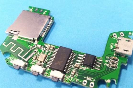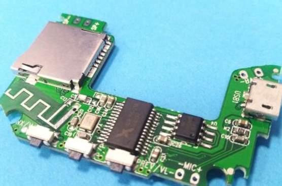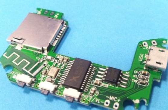
Chips are also known as microcircuit, microchip, and integrated circuit (lC). A small piece of silicon containing an integrated circuit, often part of a computer or other electronic device. Chip as a hot topic in recent years, more and more attention by the people. As an electronic SMT patch manufacturer, we are in touch with chips every day, but how is the chip made? I believe that many friends are not very clear, then the next by Shenzhen SMT plant kingford- to briefly describe the chip manufacturing process, I hope to give you some help!
1, silicon purification to make wafers
The sand is purified through related processing processes, and then through a series of procedures to obtain silicon, and then made into very pure silicon rods. Silicon rod is the material of quartz semiconductor, which is used to make integrated circuit, and slicing it is the wafer which is needed to make chip. Silicon wafers are the substrate on which chips are made. Silicon ingots are mechanically cut into thin silicon circles to facilitate etching of integrated circuit chips.
2. Wafer coating
Wafer coatings are resistant to oxidation and temperature, and the material is photoresistant.
3, wafer lithography development, etching
The process uses chemicals that are sensitive to ultraviolet light, which softens them. The shape of the chip can be obtained by controlling the position of the shading. Silicon wafers are coated with photoresist so that they dissolve in ultraviolet light. This is where the first shading can be applied, so that the part of the UV light is dissolved, which can then be washed away with a solvent. So the rest of it is the same shape as the shade, and that's what we want. This gives us the silica layer we need.
4. Add impurities
In this process, ions are implanted into the wafer to generate the corresponding P and N semiconductors. The process is to start from the exposed area on the silicon wafer and put it into a mixture of chemical ions. The process will change the way the dopant zone conducts electricity, allowing each transistor to switch on, off or carry data. Simple chips can use only one layer, but complex chips often have many layers, and the process is repeated over and over again, with different layers connected by opening Windows. This is similar to the production principle of the layer PCB board. More complex chips may require multiple layers of silica, which can be achieved through repeated lithography and the process above, forming a three-dimensional structure.
5. Wafer testing
After the above several processes, the wafer is formed into a lattice of grains. The electrical characteristics of each grain were detected by means of needle measurement. Generally, the number of grains of each chip is huge, and organizing a pin test pattern is a very complex process, which requires mass production of models with the same chip specifications as far as possible during production. The larger the volume, the lower the relative cost, which is one of the reasons why mainstream chip devices are so cheap.

6. Chip packaging
Wafer fabrication is fixed, pins are bound, and various packaging forms are produced as required, which is why the same chip core can have different packaging forms. For example :DIP, QFP, PLCC, QFN, etc. Here is mainly by the user's application habits, application environment, market form and other peripheral factors to decide.
7. Testing and packaging
After the above process, the production of the chip has been completed. This step is to test the chip, remove the defective products, and package it.
2. Reasons and solutions for the pinching of PCBA processing solder joints
Solder joint pulling tip refers to the fact that the solder on the PCBA solder joint is raised and has a distinct tip shape, which is called solder joint pulling tip. The common process of PCBA processing and welding is mainly divided into three parts: one is SMT reflow welding, two is DIP wave welding, and finally is manual soldering iron welding. PCBA solder joint tip phenomenon generally occurs in manual welding process and DIP crest welding process, because the solder joint tip must be caused by the combination between liquid and solid, and manual welding and DIP crest welding material is a liquid or solid into a liquid welding, so there is a solder joint tip phenomenon. Next, Shenzhen PCBA processing manufacturer -kingford- for you to explain the PCBA processing solder joint pointed reasons and solutions, hope to bring you some help
1. Reasons for the pointed solder joint during manual welding of PCBA
(1) In the PCBA manual welding, the iron head on the hand of the operator is quickly removed when the solder is not completely melted and fixed; ② Caused by low temperature during welding. But most of the reasons are the flame iron head removed too late, welding time is too long, the flux is vaporized, that is to say, the point is related to temperature and operation; (3) Manual welding is not a good grasp of the welding method; (4) There are impurities in the Luoiron head, leading to the tip of the solder joint;
The solution:
(1) Put the tin strip on the iron head, and evenly coat the solder on the iron head, so that the iron head is evenly coated with a layer of tin. When welding, the wire is sent by hand, and the tin is evenly spread on the welding head with an electric collard. (2) If you see some welding impurities on the iron head, you can put the iron head on the soaked sponge to clean up; (3) The iron head is formed into a 45 degree Angle, and the welding pad and the element foot are heated in advance. The tip of the soldering iron head shall not stand against the copper position of the PCB board, so as not to burn the board into a trace; The iron head is best along the line direction; ④ Introduce the tin wire from the contact surface of the element foot and the soldering iron. When the tin wire melts, master the speed of the wire. Remove tin wire when tin has spread throughout the pad. The tin line can not be directly on the iron head, to prevent the flux from burning black, the whole tin time is about 1 ~ 2 seconds; ⑤ Remove the tin wire and place the furnace on the pad; It takes about one to two seconds. When only slight smoke comes out of the solder, you can remove the iron to solidify the solder joint.
I. Reasons for the tip of the solder joint during DIP crest welding
① The drawing point has a great direct relationship with the wave soldering temperature. Low preheating temperature and low soldering temperature will make the soldering tin unable to shrink effectively due to insufficient temperature after the wave crest. The low temperature of molten tin increases the viscosity of molten tin and intensifies the formation of drawing point. Flux also has a lot to do with the tip. When the activity of the flux is not enough or the concentration decreases, the flux is not capable of deoxidizing and reducing the surface tension, so that the molten tin can not shrink effectively when leaving the tin furnace to form a drawing point; When the chain speed is too fast, the excess solder may also be too late to be pulled back to the tin furnace, causing the tip. ④ the welding foot should be cut short if the welding foot is worn too long. It is recommended that the outlet (L) of the welded foot be less than 2mm.
The solution:
(1) According to the PCB size, PCB layer, the number of components, the size of the solder plate, etc., set the preheating temperature and the temperature of the tin furnace. The preheating temperature is 90~130℃, and the temperature of the tin furnace is 260±10℃; ② The upper limit of preheating temperature is adopted when there are more mounted components. The crest height is generally controlled at 2/3 of the thickness of the printed board. ③ Pin forming of plug-in components requires that the pin of the component is exposed to the PCB board and welded with 2~3mm. (4) Increasing flux concentration, activity and spraying amount, increasing flux spraying pressure and improving its penetration are conducive to the elimination of pulling tip. ⑤ Adjust the chain speed and the contact Angle between the track and the tin surface.


