
Контрактное производство электроники под ключ в Китае
Шэньчжэнь, район Баоань, улица Фуюн, улица Фуцяо, район 3, промышленный парк Лонгхуй 6

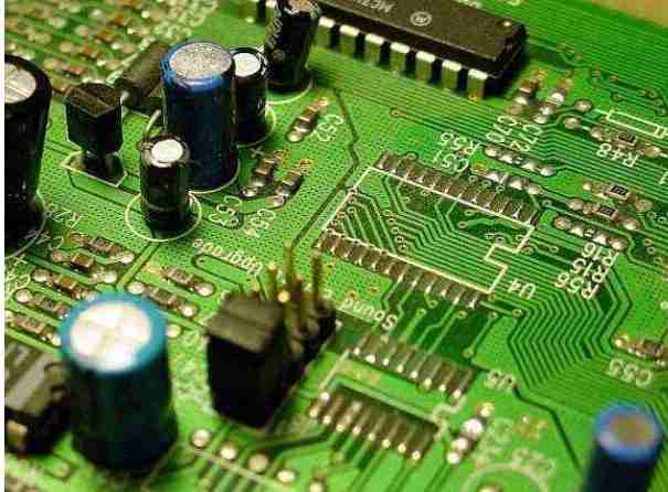
BAG and other difficult chip repair process, equipment, personnel need to want to be high requirements, let's have a look!
1. Requirements on process equipment for rework
Naturally, convection rather than radiation is the preferred method for reworking BGA/CSP components, and soldering irons (heat conduction) are not ideal. Even in conventional BGA rework, it is difficult to use IR because ceramic heaters do not cool quickly and therefore the time above reflux temperature is difficult to control; The use of convection is easy to carry out strict process control, conducive to the establishment of a good, repeatable temperature curve, will not cause the components to be overheated, or above the reflux temperature for a long time.
Standard reflux consists of three temperature zones (Table 1) : preheating zone, insulation zone and reflux zone. After reflux, the PCB board is cooled to below 100℃. The welding process becomes critical when lead-free assembly is used. The high temperature required to be lead-free (up to 235℃) and the sensitivity of BGA/CSP to high temperatures make it easy to damage components during an incorrect temperature rise process.
The latest rework equipment uses four additional heating zones and one system-controlled cooling zone. Adding a controlled preheater to the rework equipment can meet the lead-free process requirements. Although the basic requirements for setting any temperature curve are familiar, setting the correct, ideal curve requires experience and patience.
2. Requirements for temperature of components
Generally speaking, when the temperature of the gas used exceeds 300℃, BGA will appear due to the warping problem, resulting in the corner of the bridge, which is known as the "dog ears" phenomenon. Therefore, 265℃~285℃ was taken as the highest gas temperature in the reflux area. On the other hand, lead-free solder paste reflux requires relatively high temperature, the commonly used peak welding temperature of 235℃.
The maximum temperature of the outer edge of the component specified by the supplier of the component is 265℃. The most commonly used temperature range is 240 ℃ ~250℃. These temperatures are very close to the welding temperature of 225℃~233℃. More seriously for lead-free, the time allowed for the component to stay above the reflux temperature is a three - to four-fold decrease from 60-90 seconds for eutectic solder to 15-30 seconds for lead-free solder. That means reworking equipment must be able to heat up quickly and cool down quickly.
3. Compatibility of components
Many manufacturers are transitioning to lead-free solder balls. Eutectic solder balls are still the standard of choice in the United States, and component manufacturers have adopted lead-free solder balls as the standard. If lead-free components can be used in common welding processes, there is no need for major changes in manufacturing processes. Therefore, components are toward the trend of lead-free development, manufacturers only need to produce a component product, can meet the needs of the production enterprises using lead-free or lead process
4. Temperature difference setting
The temperature difference (the evenness of the temperature distribution) between the surfaces of the components is a factor that must be considered for high-quality rework and assembly. Generally, an increment of 10℃ is considered acceptable. The temperature difference between the upper and lower parts of the device is another important factor. The new lead-free welding process requires a temperature difference of 5℃ preferably. On a small PCB (such as the circuit board of a mobile phone) using smaller components, it is not difficult to achieve this temperature difference control, on the contrary, the larger the BGA, the more difficult it is to achieve this temperature difference.
5, temperature curve control
To ensure that the solder joint does not crack, the temperature needs to be better controlled, including heating, rapid heating and cooling, especially at the bottom of the board. The heating plate cannot be heated and cooled quickly, so it is not suitable for the application of lead-free welding process.

The heating process in the reflux furnace is controlled by the speed of the conveyor belt, while in the rework process, the PCB cannot move due to solder joints melting or the PCB at a glass transition temperature above about 125℃ (depending on the material used in the substrate). Therefore, it is not advisable to move the PCB during the rework process, nor is it possible to control the time above the reflux temperature. IR ceramic heaters are an example of those that do not meet the latter requirements. Retention time above reflux temperature ranges from 15 to 30 seconds for lead-free solder paste and typically 45 to 60 seconds for clean-free eutectic solders.
6, the principle of setting the temperature curve has three points, that is, enough to melt the solder and form intermetallic compounds; Sufficient to activate the flux and produce a wetting effect; And use temperatures low enough not to damage components and PCBS. Lead-free solder uses a completely different rework temperature curve than leaded eutectic solder, and the tolerance is very small, difficult to achieve. Here is an example of how the temperature curve for a lead-free weld differs from the standard curve for a eutectic solder, where temperature control and rapid warming and cooling are critical
As mentioned earlier, the time to reach the reflux temperature above is generally limited to 30 seconds, some even as little as 15 seconds. However, the difference in temperature between the entire surface and the upper and lower surfaces is important to get the solder joint to the desired temperature. The larger the component is, the greater the difference in its thermal expansion coefficient CTE. If the thermal expansion from the center of the component to the corner of the component is inconsistent with the expansion of PCB, the solder joint located in the corner of the component will be in a state of stress, which is particularly critical for no 7, lead solder joint.
Lead-free products are tested differently from those containing lead
In common eutectic welding process, the solder joint with rough surface is usually regarded as unqualified product. However, for lead-free solder joints, this is a normal phenomenon. Companies transitioning to lead-free need to implement new quality standards. Visual inspection equipment needs to control the light in the front, without a strong backlight, or the image will look too bright and glowing.
X-Ray, the traditional method of detecting BGA/CSP, can still be used, however, X-ray does not detect the appearance quality of the solder joint. Recent two years of popular visual inspection equipment, in the current economic predicament, is the only inspection equipment for some enterprises. Compared with the X-ray testing equipment of $75,000 ~ $120,000, the cost of this testing equipment is generally much cheaper, only $20,000 ~ $25,000. Another difference between X-ray and visual inspection equipment is that the visual inspection equipment can see the welding points above and below the welding ball, which can detect and determine the formation of intermetallic combination. This is difficult to do even with extremely expensive X-ray equipment.
The difference between BGA and CSP devices should also be taken into account when selecting visual inspection equipment. The mass of CSP is smaller than that of BGA. If the process of reflux furnace is not properly controlled, the temperature of CSP will be very high. If a CSP uses the same board as a large BGA (which is common), visual inspection is more necessary. It must be noted that the removal height of the CSP is 0.007 "~ 0.008" (0.2mm), while the removal height of the BGA is 0.0018 "~ 0.020" (0.5mm).
Find SMT manufacturer
kingford is equipped with automatic SMT SMT workshop, equipped with automatic loading machine, automatic solder paste printing machine, automatic SPI solder paste detector, imported SMT SMT SMT machine, large 20-temperature reflow welding equipment, 3D around X-Ray detector, ultra clear AOI optical detector, BGA repair table and other high precision equipment. Plug-in, post welding, testing, assembly of a full set of assembly lines. Can paste 0201, 0.3 spacing BGA chip, the current company patch products have X86 platform server motherboard, tablet computer motherboard, Android system motherboard, military grade and other high precision products, welcome all the big men to come to audit factory, common development.
SMT process incoming material inspection
2023-02-21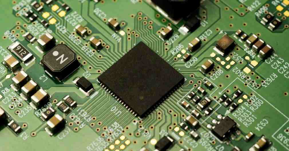


Достаточно загрузить файлы Gerber, BOM и проектные документы, и команда KINGFORD предоставит полное предложение в течение 24 часов.