The negative current flowing through the signal return path is exactly the same as the positive current flowing into the signal line. Moreover, right in front of the signal, AC current flows through a capacitor consisting of the signal line and the signal return path, completing the signal loop.
From the battery's point of view, once the design engineer connects the battery's lead to the front end of the transmission line, there is always a constant amount of current flowing out of the battery and keeping the voltage signal stable. One may ask, what kind of electronic device behaves like this? A constant constant current value is maintained when you add a constant constant voltage signal, which of course is resistance.
In the case of the battery, as the signal travels along the transmission line, every 10 Ps time interval, an additional 0.06 inches of the transmission line is charged up to 1V. The added charge from the battery ensures that a steady current is maintained from the battery, and constant current is absorbed from the battery. The transmission line acts as a resistance, and the resistance is constant. We call this the surge impedance of a transmission line.
Similarly, as the signal travels forward along the transmission line, it constantly probes the electrical environment of the signal line for every certain distance it travels and attempts to determine the impedance of the signal as it travels further forward. Once the signal has been added to the transmission line and is traveling along it, the signal itself is constantly testing how much current is needed to charge the length of the transmission line in 10ps intervals and keep that portion of the line charged to 1V. This is exactly the instantaneous impedance value that we want to analyze.
From the point of view of the battery itself, if the signal travels at a constant speed along the transmission line, and the transmission line is assumed to have a consistent cross-section, then each fixed length of the signal propagates (such as the distance the signal travels in a 10ps time interval), The same amount of charge needs to be taken from the battery to ensure that this section of line is charged to the same signal voltage. Every time the signal travels a fixed distance, it draws the same current from the battery and keeps the signal voltage consistent. As the signal travels, the instantaneous impedance is the same everywhere on the transmission line.
When a signal travels along a transmission line, if the signal travels at a consistent speed all over the line and the capacitance per unit length is the same, then the signal will always see exactly the same instantaneous impedance as it travels. Since the impedance remains constant throughout the transmission line, we give a specific name to denote this characteristic or characteristic of a particular transmission line, called the characteristic impedance of the transmission line. Characteristic impedance is the value of the instantaneous impedance seen by the signal as it travels along the transmission line. A transmission line is said to have a controlled impedance if the characteristic impedance seen by the signal remains consistent at all times along the transmission line.

Characteristic impedance of transmission line is a very important factor in design
The instantaneous impedance or characteristic impedance of a transmission line is a very important factor affecting signal quality. If the impedance between adjacent signal intervals is consistent during transmission, the signal can travel forward quite smoothly, so the situation is quite simple.
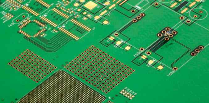
In order to ensure better signal quality, the goal of signal interconnection design is to ensure that the impedance seen during signal transmission remains as constant as possible. The main point here is to keep the characteristic impedance of the transmission line as constant. So the design, production and manufacture of controlled impedance PCB board becomes more and more important. Any other design tricks such as considerably reducing the length of the goldfinger, terminal matching, Daisy chain connections or branch connections are designed to ensure that the signal sees a consistent instantaneous impedance.
Calculation of characteristic impedance
From the above simple model we can deduce the value of the characteristic impedance, that is, the instantaneous impedance seen during the transmission of the signal. The impedance Z seen by the signal at each propagation interval is consistent with the basic definition of impedance
Z = V/I
The voltage here V refers to the voltage of the signal added to the transmission line, and the current I refers to the total amount of charge taken from the battery at each interval δt, so
I = the delta Q/delta t


