
Контрактное производство электроники под ключ в Китае
Шэньчжэнь, район Баоань, улица Фуюн, улица Фуцяо, район 3, промышленный парк Лонгхуй 6

(1) The printed circuit is not allowed to have a cross circuit, for the possible cross lines, you can use "drill", "wind" two ways to solve. That is, let a lead from other resistance, capacitance, the gap at the foot of the audion "drill" in the past, or from the possible cross of a lead end "wound" in the past, in special cases how to circuit is very complex, in order to simplify the design also allows the use of wire straddle, to solve the problem of cross circuit.
(2) Resistance, diode, tubular capacitor and other components have "vertical", "horizontal" two ways of installation. Vertical refers to the component body perpendicular to the circuit board installation, welding, its advantage is to save space, horizontal refers to the component body parallel and close to the circuit board installation, welding, its advantage is that the mechanical strength of the component installation is better. These two different mounting components, components on the printed circuit board hole spacing is not the same.
(3) The ground point of the same level circuit should be as close as possible, and the power filter capacitor of this level circuit should also be connected to the ground point of the level. In particular, the base of the transistor, the emitter of the ground point can not be too far away, otherwise because the copper foil between the two ground points is too long will cause interference and self-excitation, the use of such a "point grounding method" circuit, the work is more stable, not easy to self-excitation.
(4) the total ground wire must be strictly in accordance with the high frequency - medium frequency - low frequency one level according to the order of weak current to strong current principle, must not randomly turn over and over, between the level would rather wiring long point, also want to comply with this provision. In particular, frequency conversion head, regeneration head, frequency modulation head grounding wire arrangement requirements are more strict, if there is improper will produce self-excitation so that it can not work.
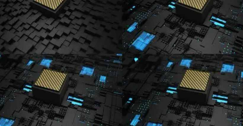
V. Functions of printed circuits in electronic equipment
(1) Provide mechanical support for fixed and assembled electronic components such as integrated circuits.
(2) Realize wiring and electrical connection or electrical insulation between various electronic components such as integrated circuits.
(3) Provide required electrical characteristics, such as characteristic impedance, etc.
(4) Provide solder resistance graphics for automatic soldering, and provide identification symbols and graphics for assembly, inspection and maintenance of components.
Vi. High speed circuit
It is generally believed that if the frequency of a digital logic circuit reaches or exceeds 45MHZ~50MHZ, and the circuit working on this frequency has accounted for a certain portion of the whole electronic system (for example, 1/3), it is called a high-speed circuit.
In fact, the harmonic frequency of the edge of the signal is higher than the frequency of the signal itself. It is the rising and falling edge of the signal changing rapidly (or the jump of the signal) that causes the unexpected result of the signal transmission. Therefore, it is generally agreed that if the line propagation delay is greater than 1/2 rise time of the driving end of the digital signal, such signals are considered to be high-speed signals and produce transmission line effect. The transmission of the signal occurs at the moment when the state of the signal changes, such as the time of rise or fall. The signal passes a fixed period of time from the driver to the receiver. If the transmission time is less than 1/2 the rise or fall time, then the reflected signal from the receiver will reach the driver before the signal changes state. Conversely, the reflected signal will reach the driver after the signal changes state. If the reflection is strong, the superimposed waveform may change the logical state.
7 ·V_CUT
One way to form the circuit board is to cut a straight line at the same position on the upper and lower sides of the board but not cut so that the grooves forming a V shape from the side of the board can be broken manually or by using a fixture, so it is called V_CUT
Eight. Goldfinger
It refers to some circuit boards, such as network cards, on the edge of the panel a root of gold-plated wire, because of its shape like fingers, so called gold fingers

PCB board serpentine use
Any line on the PCB will cause time delay to the signal when passing through the high frequency signal. The main function of the snake line is to compensate the part of the "same group of correlation" signal line with small delay, which is usually not or less than other signals through another logic processing; The most typical is the clock line, which usually does not require any other logical processing and thus has a smaller delay than other associated signals.
The isobar length of high-speed digital PCB board is to keep the delay difference of each signal within a range and ensure the validity of the data read by the system in the same cycle (when the delay difference exceeds one clock cycle, the data of the next cycle will be misread). Generally, the delay difference is required to be no more than 1/4 clock cycle. The line delay difference per unit length is also fixed. Copper thickness is related to the laminar structure, but too long wire will increase the distributed capacitance and distributed inductance, affecting the signal quality, so the clock IC pin is generally connected to both ends of RC, but the snake wire does not play the role of inductance, on the contrary, inductance will make the signal in the ascending element of the high-order harmonic phase shift, resulting in signal quality deterioration, so the distance between the snake wire is required to be at least twice the width of the line. The smaller the rise time, the more susceptible the signal is to distributed capacitance and distributed inductance.
Because different applications have different functions, if the snake in the computer board, it mainly plays a role of filtering inductance, improve the anti-interference ability of the circuit, the snake in the computer host board, mainly used in some clock signals, such as CIClk, AGPClk, its role has two points: 1, impedance matching 2, filtering inductance. For some important signals, such as HUBLink in INTEL HUB architecture, there are 13 in total, running 233MHz, which requires strict equal length to eliminate hidden dangers caused by time delay. Winding is the only solution. Generally speaking, the distance between the lines of the serpentine line > Is equal to 2 times the line width. The snake line on PCI board is to adapt to the line length requirements of PCI 33MHzClock. If in the general ordinary PCB board, is a distributed parameter LC filter, can also be used as a radio antenna inductor coil, short and narrow snake wire can do fuse and so on.


Достаточно загрузить файлы Gerber, BOM и проектные документы, и команда KINGFORD предоставит полное предложение в течение 24 часов.