
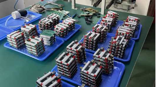
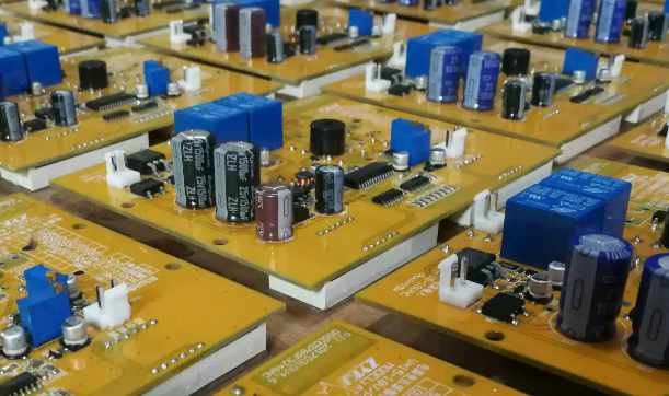
Контрактное производство электроники под ключ в Китае
Шэньчжэнь, район Баоань, улица Фуюн, улица Фуцяо, район 3, промышленный парк Лонгхуй 6

(1) There is water or water vapor in the hole before the film.
(2) Small hole with height-thick-diameter ratio, taking the hole of 0.5mm as an example.
(3) Too long film and development time.
The main reason that water vapor stops in the hole is that water can reduce the viscosity of resist and make it flow into the hole faster. Holes with high thickness to diameter ratio are more prone to cavity problems because they are more difficult to dry. Corrosion resistance in small holes is also difficult to develop. Longer time before development also allows more resist to flow into the hole. Surface treatment and automatic film connection, more prone to problems.
C. Avoid holes at the mouth or side of the hole
The best and simplest way to avoid holes or holes is to increase the degree of drying after surface treatment. If the hole is dry, there will be no hole mouth or hole edge cavity. Long placement time and poor development will not result in holes or holes.
After increasing the drying, the placement time between the film and development should be as short as possible, but the stability should be considered. If the following conditions occur, orifice or hole side cavity may occur (not previously) :

(1) After the installation of new surface treatment equipment and drying equipment.
(2) The surface treatment equipment and drying section are dysfunctional.
(3) Production of small hole plate with high thickness to diameter ratio.
(4) Dry film with corrosion resistance change or thickness change.
(5) vacuum laminating machine.
In the worst and rare case, the resist forms a coating in the hole. As the mask layer is pushed into the hole 50-70 microns deep, because the mask will prevent the solution from entering, it will appear as a general edge cavity at one end of the hole, and the cavity will extend to most of the holes. From the other end of the hole, the thickness of the coating will be thinner the closer it is to the center of the hole.
Many printed board factories have been converted to direct plating process, which is sometimes connected with the laminating machine. If the back section is not sufficiently dried, holes and holes may occur. To dry the hole fully, the drying section needs to be very full.
4. Voids associated with mask holes
In the mask process, if the mask is not good, the etching agent will enter the hole and etch the deposited copper. The mechanism damage of the mask is dynamic, and there are few holes in the upper and lower masks together.
Similarly, the mask is very weak, resulting in negative pressure in the hole, which eventually leads to the defect of the mask hole. This mask can reduce the negative pressure, and the mask on the opposite side is easier to survive. The mask on one side is destroyed, the etching agent enters the hole, and the copper on the side of the broken mask is etched away first. On the other hand, the mask blocked the outlet of the etching agent, and the etching liquid communicated too little, so the cavity pattern was relatively symmetrical, showing that one end was thick copper and the other end was thin. Depending on the extent of the mask damage, the situation is different. In extreme cases, all the through-hole copper is etched away.
5. Direct plating
Direct electroplating avoids the traditional chemical precipitation of copper, but there are three kinds of pretreatment process steps; Such as: palladium matrix process, carbon film process, organic conductive film process.
Cavities can be formed by the deposition of monomers and polymer components under any conditions that affect the deposition of catalysts, or by the deposition of polymer conductive films. Most carbon, graphite, and palladium film processes rely on proper pore wall adjustment, using polymer electrolyte cations with an organic catalytic layer containing opposite charges. In order to achieve better catalytic adsorption. Naturally, it has been proven that good process procedures such as pore wall cleaning, adjustment, and catalytic deposition have been properly applied in direct plating processes. Of course, the specific problems of chemical copper sinks, such as hydrogen production, do not occur here.
In the use of direct plating process, if not in accordance with the conditions recommended by the potion supplier, there are often some special problems. For example, in the carbon film process, it is generally not recommended to scrub the surface after the carbon film is deposited, because the brush will remove the carbon film particles at the edge of the hole. In this case, it is difficult for the plating process to get from the copper surface to the center of the hole in time, if at all.
Plating can also be done from the opposite side if the orifice carbon film on one side of the board is brushed away. But the electroplating result is gradually weakened, plating copper may not be connected with the other copper surface. The result is similar to the mask rupture in the mask hole process. In the carbon film or graphite process, if the use of pumice powder injection after catalytic deposition, the cavity will also occur. The ejected pumice powder particles may enter the pore at a high rate and wash away the catalytic layer particles. On the other hand, the graphite process seems to tolerate pumice stucco treatment.


Достаточно загрузить файлы Gerber, BOM и проектные документы, и команда KINGFORD предоставит полное предложение в течение 24 часов.