
Контрактное производство электроники под ключ в Китае
Шэньчжэнь, район Баоань, улица Фуюн, улица Фуцяо, район 3, промышленный парк Лонгхуй 6

With the continuous progress of science and technology, there are more and more types of electronic products at present. In order to determine the feasibility of the scheme, design engineers will keep making samples for testing in the early stage of design. Then what is the charge of PCBA making samples? And how much does it cost? Electronic product developers often hear machine fees and engineering fees when they make SMT samples or produce in small batches in PCBA processing plants. SMT patch processing emphasizes fast and efficient production. General SMT patch workshops will carry out non-stop production, and machine shutdown and line change will increase production costs and reduce profits. For some batch relatively small order will often charge the machine fee.
PCBA proofing, generally according to the information provided by the customer and process requirements to charge. For example: the number of boards, process requirements, ink color, board thickness, difficulty, etc., a comprehensive assessment of the price. It is not a general how much it costs to make a pcb sample. The engineering cost refers to the production of data files, the production of steel mesh, the debugging of equipment and the replacement of SMT line. Due to the small order, the minimum consumption level has not been reached, so the customer needs to bear the engineering cost.
First, PCB small batch proofing said high charge, mainly does not refer to boot loss, but time loss. It means that before SMT patch processing, no matter mass SMT patch processing or small batch SMT patch processing, the preliminary work needs to be done is the same, such as SMT patch processing machine programming, PCB positioning, starting up the first piece confirmation and so on. In fact, the time in the patch is very short, and then the workers need to spend time constantly staring at the attached PCB board. So in the case of small quantity, the so-called loss, is more time loss.
Second, with the same time cost, the production efficiency of SMT patch processing in large quantity is higher, so that we will not waste time on the preliminary work after one morning or one day of production. Sometimes encountered small customers, processing volume is very small, the price will be very cheap, in fact, it is not. The preliminary work of PCBA proofing in large and small batches is the same. The programming of SMT mounter, PCB positioning, and confirmation of the first piece after starting up are all done in the same way as long as the mounter is installed. Therefore, the project fee will be charged in small batches, or the start-up fee is called in some places. Otherwise, the amount is too little, not enough labor costs, machine loss, basically wasted on the time in and out. This is why PCB small batch proofing will be charged additional engineering fees.
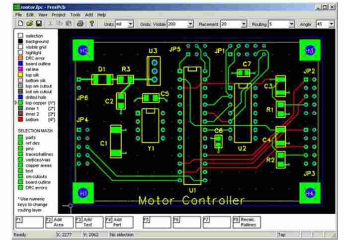
2. Significance and function of PCB layer
PCB is a multi-layer structure of the product, different layers have different uses, next, Shenzhen PCB design company kingford to introduce the significance and function of the PCB layer.
The significance and function of PCB layer
1. TOP LAYER (top wiring layer) :
Design for the top copper foil wiring. If it is a single panel, there is no layer.
2. BOMTTOM LAYER (bottom wiring layer) :
Design for the bottom copper foil wiring.

3, TOP/BOTTOM SOLDER (top/bottom solder green oil layer) :
The top/bottom layer is coated with solder resistance green oil to prevent tinning of copper foil and maintain insulation. Weld green oil window on pad, through hole and non-electrical wiring of this layer.
The welding pad will open a window by default in the design (OVERRIDE: 0.1016mm), that is, the welding pad is exposed to copper foil, and the outer expansion is 0.1016mm, and the tin will be raised during wave soldering. No design changes are recommended to ensure weldability.
The overhole will be windowed by default in the design (OVERRIDE: 0.1016mm), that is, the overhole copper foil will be expanded by 0.1016mm and will be tinned during wave soldering. If the design is to prevent SOLDER from passing through the hole, do not expose copper, you must check the PENTING option of SOLDER MASK (solder window) to close the pass through the hole window.
In addition, this layer can also be separate for non-electrical wiring, then welding green oil corresponding window. If it is on the copper foil wire, it is used to enhance the ability of wire current, solder treatment; If it is on the non-copper foil wire, it is generally designed to do identification and special character silkscreen printing, which can save the production of character silkscreen layer.
4. TOP/BOTTOM PASTE (top/bottom paste) :
This layer is generally used for solder paste in SMT reflow soldering process of patch components. It has nothing to do with the printed board manufacturer's board. It can be deleted when GERBER is exported and can be retained as default in PCB design.
5. TOP/BOTTOM OVERLAY (top/bottom Silk-screen layer) :
Design for a variety of silk screen logo, such as component digit, character, trademark, etc.
6. MECHANICAL LAYERS:
Design for PCB mechanical shape, default LAYER1 is the shape layer. Other LAYER2/3/4 etc. can be used for mechanical dimensioning or special purposes. For example, when some boards need to make conductive carbon oil, LAYER2/3/4 etc. can be used, but the purpose of the layer must be clearly marked on the same floor.
7. KEEPOUT LAYER (Disallow wiring layer) :
Designed to prohibit wiring layer, many designers also use PCB MECHANICAL appearance. If there are KEEPOUT and MECHANICAL LAYER1 on the PCB at the same time, the integrity of the appearance of these two layers is mainly looked at, and MECHANICAL LAYER1 is generally adopted as the standard. It is suggested that MECHANICAL LAYER1 should be used as the outline LAYER as far as possible in the design. If KEEPOUT LAYER is used as the outline, do not use MECHANICAL LAYER1 again to avoid confusion!
8. MIDLAYERS (Intermediate Signal layer) :
Used for multilayer, can also be used as a special purpose layer, but must be clearly identified in the same layer of the purpose of the layer.
9. INTERNAL PLANES:
Used for multilayer panels.
10. MULTI LAYER:
Through hole welding layer.
11, DRILL GUIDE (drilling location layer) :
The center positioning coordinate layer of the pad and the hole through the hole.
12, DRILL DRAWING (drilling description layer) :
Weld pad and through hole bore size description layer.
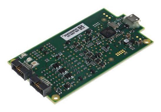
Shenzhen kingford Co., Ltd. has a team of professional component purchasing specialists and incoming materials analysis and control engineers responsible for component purchasing and quality control, and several professional PCBA production engineers responsible for SMT production line operation. Business, purchasing and production departments can cooperate with the review of new orders, production arrangement and product testing.
The production line is equipped with SMT processing equipment of Gikonda, Juki, Suneast and other brands to ensure the fast production and delivery time. Currently, we can provide 5-500 sets of circuit board proofing urgent service. The factory has passed ISO9001-2008 quality management system to provide customers with higher quality PCBA proofing services.


Достаточно загрузить файлы Gerber, BOM и проектные документы, и команда KINGFORD предоставит полное предложение в течение 24 часов.