
Контрактное производство электроники под ключ в Китае
Шэньчжэнь, район Баоань, улица Фуюн, улица Фуцяо, район 3, промышленный парк Лонгхуй 6

In order to study EDA technology and SCM technology in depth, the following key board, EDA technology and SCM technology application analysis, in order to effectively improve the technical level of software development, promote the long-term development of software development industry. In the study of EDA technology and single chip technology in the application of the keyboard, the use of EDA related software and programming download software, as well as the corresponding single chip microcomputer and supporting compilation software. Key board is generally selected matrix key board, has a wide range of practicability.
The application of EDA and single chip microcomputer in keyboard
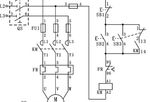
In keyboard Settings, keys are set through the focus of the line and column lines, the two ends of the key switch and the line and column lines respectively connected. The connection of the line is through the pull-up resistance, so the line is in high level without any operation. When the key operation is carried out, the line will affect the level of the line, thus causing the change of the level of the line. The level of the line varies with the level of the column line. If the column line is high, the line is high. This is used in key recognition.
According to the keyboard key arrangement basis, in the use of EDA technology and single-chip technology, the matrix keyboard column line and line is used by the multi-key sharing, reduce the chip I/O interface possession, greatly improve the use of the keyboard speed. In the keyboard, the use of EDA technology and single-chip microcomputer technology to connect the signal, when the line and line affect each other, you can effectively control the key, to achieve the key closure. At the same time, through the combined application of EDA technology and SCM technology, can effectively control the switch of the keyboard, the keyboard operation at any time, so as to complete the corresponding work according to the relevant instructions.
EDA technology and SCM technology in the application of the keyboard, can help the keyboard to complete a variety of complex operations, in order to achieve effective control of the screen display, so as to switch different pictures, complete different tasks. The promotion and application of EDA technology and SCM technology in each industry, to the continuous improvement of economic efficiency of each industry provided , promoting the long-term development of Chinese software industry, is of great significance for promoting the modernization construction of our country.
As a microelectronic IC learner, there is also a course in this semester: "Microelectronic devices", today I will talk about the basic devices: CMOS devices and circuits. We'll talk about latches and triggers later.

Today's main content is as follows:
· Brief introduction of MOS transistor structure and working principle
·CMOS unit circuit and layout
·CMOS gate circuit
· Power representation of CMOS
To be honest, CMOS is more micro electronic devices, micro electronic devices are really difficult... Here are a few things you might want to know about doing digital design (I'll add more later if necessary).
1. Brief introduction of structure and working principle of MOS transistor
It is more or less known that the main function of a transistor in a digital circuit is an electronic switch, which is turned on or off by a voltage or a current. There are roughly two kinds of transistors: One is bipolar junction transistor and the other is metal-oxide-semiconductor field-effect transistor (MOSFET or MOS). metal-oxide-semiconductor field effect transistor). Here we mainly talk about MOS, BJT in the current digital IC design is not the mainstream technology.
2. MOS transistors are divided into PMOS and NMOS, which type of MOS depends on the substrate and doping concentration. As for how it is formed, it is too complicated to explain in a few words, so let's skip it and look directly at their cross section diagram and briefly explain how they work (NMOS are taken as examples below).
The cross-sectional structure of the NMOS transistor is shown as follows:
IC design: CMOS devices and their circuits
The substrate is a silicon substrate (where the Body Si is), the top is a conductive gate, and the middle is an insulating layer composed of silica. In the past, the gate * was made of metal, so it was called metal-oxide-semiconductor. Now the gate * uses poly. In the MOS structure, a capacitor is formed by silica between a metal (polysilicon) and a semiconductor substrate.
Well, it doesn't matter if you don't understand the above paragraph, but remember that in the above NMOS transistor, the substrate is P-type, and there are two N-type doping regions on the substrate called Source and Drain. (You can define the left side as the drain and the right side as the source.) Since the device is symmetrical at this time, S and D are not really determined until the power supply and ground are connected), the upper middle is called Gate * (Gate), which is the three electrodes of NMOS (actually MOS is a 4-terminal device, and its substrate is also a terminal). Here's how they work.
As we said, the function of a transistor is roughly a switch that turns on and off under the control of a current or voltage. In the case of an NMOS transistor, we now apply a voltage to it to make it work:
IC design: CMOS devices and their circuits
Add a voltage, and the so-called source * is the source of the electrons; The so-called leakage *, is equivalent to the leakage of the electron opening; And the grid in the middle, *, acts like a control switch: On the one hand, by controlling the high level voltage applied in the grid *, there is a channel between the source and drain, and the electrons flow from the source to the drain through the channel, and the direction of the current is from the drain to the source, so as to conduct electricity, that is, when the "switch" is opened (due to the formation of N channel, that is, electronic conduction, so it becomes N-type CMOS). On the other hand, a low level voltage is applied to the gate by the control, so that the channel is off, so that the source and drain are off, that is, when the "switch" is off. This is the structure and workflow of NMOS. (PMOS work in the opposite way: turn on by controlling the low level voltage applied to the gate, and turn off the channel by controlling the high level voltage applied to the gate.)
Circuit board processing process
2023-03-27
Достаточно загрузить файлы Gerber, BOM и проектные документы, и команда KINGFORD предоставит полное предложение в течение 24 часов.