
Контрактное производство электроники под ключ в Китае
Шэньчжэнь, район Баоань, улица Фуюн, улица Фуцяо, район 3, промышленный парк Лонгхуй 6

Familiar with the schematic diagram and structure diagram provided by hardware;
2. Set up the package and import the PCB. Conduct component layout according to the provided structure diagram, negotiate with the hardware about the general layout direction at the initial layout stage, and communicate with the hardware at any time during the layout process.
3. After the layout is OK, the hardware will confirm the layout and send it for preliminary confirmation.
4. Confirm stacking and start wiring
5, grasp the overall wiring direction, perfect signal line protection, power line pay attention to the size of the current, cutting power supply, copper, etc. Wiring does not understand at any time and hardware communication.
6. Send the wiring to the hardware for inspection in time, and modify the PCB according to the hardware requirements.
7. The hardware confirmed that there was no problem with the layout and sent it for check. 2D and 3D drawings of PCB layout. After confirming OK.
8. Send out Gerber file and write PCB production list.
9. Send PCB samples to the board factory and reply the engineering problems of the board factory.
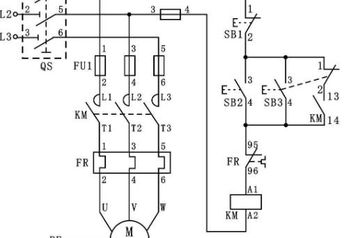
Electronic master circuit diagram collection
First, regulated power supply
1, 3 ~ 25V voltage adjustable voltage regulator circuit diagram
The voltage regulator can be adjusted in the range of 3.5V ~ 25V, the output current is large, and the adjustable voltage regulator tube circuit, so as to obtain satisfactory and stable output voltage.
Working principle: After the rectifier filter DC voltage provided by R1 to adjust the tube base *, so that the adjustment tube on, V1 on voltage through RP, R2 to V2 on, and then V3 also on, then V1, V2, V3 emission and collector voltage no longer change (its role is the same as the regulator). Adjust RP, can get a stable output voltage, R1, RP, R2 and R3 ratio determines the voltage value of the circuit output.
Component selection: Transformer T uses 80W ~ 100W, input AC220V, output double winding AC28V. 1A for FU1 and 3A ~ ** for FU2. Use 6A02 for VD1 and VD2. RP uses about 1W ordinary potentiometer, resistance value is 250K ~ 330K, C1 uses 3300µF / 35V electrolytic capacitor, C2, C3 uses 0.1µF stone capacitor, C4 uses 470µF / 35V electrolytic capacitor. R1 uses 180 ~ 220Ω/0.1W ~ 1W, R2, R4, R5 uses 10KΩ, 1/8W. 2N3055 was selected for V1, 3DG180 or 2SC3953 for V2, and 3CG12 or 3CG80 for V3
2, 10A3 ~ 15V regulated power supply circuit diagram
Whether the maintenance of the computer or electronic production can not be separated from the regulated power supply, the following introduces a DC voltage from 3V to 15V continuous adjustable voltage power supply, large current up to 10A, the circuit with temperature compensation characteristics, the most advanced standard voltage source integrated circuit TL431, so that the stability accuracy is the highest, if there is no requirement, basically can meet the normal maintenance use, The circuit is shown below.
 Its working principle is divided into two parts, part is a fixed 5V1. * The second part is another route 3 to 15V continuous adjustable high current voltage regulator circuit. The circuit is very simple, by the transformer secondary 8V AC voltage through the silicon bridge QL1 rectified DC voltage after C1 electrolytic capacitor filtering, and then by the 5V three-terminal regulator LM7805 does not use any adjustment can be produced at the output end of the fixed 5V1A regulated power supply, the power supply can be used as an internal power supply when the maintenance of the computer board. * Two parts and ordinary series type voltage regulator power supply is basically the same, the difference is the use of temperature compensation characteristics, the best standard voltage source integrated circuit TL431, so the circuit simplification, cost reduction, and voltage regulator performance is very high. In the figure, the resistor R4, the regulator TL431, and the potentiometer R3 form a continuously adjustable constant voltage source, providing reference voltage for BG2 base *. The regulator TL431 has a continuously adjustable voltage value, which determines the large output voltage of the regulator power supply. If you want to expand the adjustable voltage range, you can change the resistance values of R4 and R3. Of course, the secondary voltage of the transformer should also be increased.
Transformer power can be flexibly mastered according to the output current, secondary voltage about 15V. The rectifier tube QL for bridge rectifier uses a 15-20A silicon bridge, which is compact and has a fixing screw in the middle, which can be directly fixed on the aluminum plate of the housing for favorable heat dissipation. Adjust the pipe is a large current NPN metal shell silicon tube, because of its heat is very large, if the case allows, try to buy a large heat sink, expand the heat dissipation area, if you do not need a large current, you can also change the power of a small silicon tube, so that the volume can be smaller. The filter uses 50V4700uF electrolytic capacitor C5 and C7 in parallel, respectively, to make the large current output * stable. In addition, this capacitor should be purchased with a relatively large volume, and those with a small volume should also be marked 50V4700uF as far as possible.
When the voltage fluctuations are frequent, or when not used for a long time, it is easy to fail. Then talk about the power transformer, if there is no ability to wind their own, can not buy ready-made, you can buy a ready-made more than 200W switching power supply instead of transformer, so the voltage performance can be further improved, the production cost is not too much, other electronic components without requirements, after installation without too much adjustment can work normally.
Circuit board machining small aperture
2023-03-26

Достаточно загрузить файлы Gerber, BOM и проектные документы, и команда KINGFORD предоставит полное предложение в течение 24 часов.