
Контрактное производство электроники под ключ в Китае
Шэньчжэнь, район Баоань, улица Фуюн, улица Фуцяо, район 3, промышленный парк Лонгхуй 6

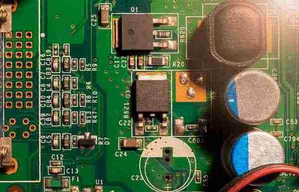
1. The electrostatic protection in the process of Pcba processing is a systematic engineering. SMT processing plant should first establish and check the anti-static basic engineering, such as ground wire, floor mat and table finishing, anti-static engineering of the environment, etc. Because once the equipment enters the workshop, if it is found that the environment does not meet the requirements and rectified, it will bring a lot of trouble. After the basic engineering of smt SMT SMT processing line is built, if it is a special site for long-line products, it shall be equipped with anti-static equipment according to the anti-static requirements of long-line products. If it is a variety of products, it shall be equipped with anti-static equipment according to the highest level of anti-static requirements.
Esd work area Do not use wood floors or lay wool, linen, chemical fiber, or ordinary leather floors in the ESD area of the production line. Instead, use an ESD floor made of ESD conductor materials, such as an ESD raised floor or an ESD floor mat on a common floor, and ground the floor effectively.
smt patch processing
Antistatic products should be selected for the ceiling materials in the anti-static area. In general, gypsum board products are allowed and ordinary plastic products are prohibited. Wall fabrics should use anti-static wallpaper, generally allowed to use plaster paint or lime paint wall, do not use ordinary wallpaper and plastic wallpaper. From the current widespread use of Shenzhen PCBa manufacturers to check is so.
The anti-static facilities in the production line of the patch processing plant shall have an independent ground wire, which shall be separated from the lightning protection wire; The ground wire is reliable and has a complete electrostatic leakage system. The workshop maintains a constant temperature and humidity environment. The general temperature is controlled at (25±2)℃ and the relative humidity is 65% 5%. The entrance shall be equipped with ion air, and the anti-static work area shall be marked with area limits and hung with warning signs in obvious places. The warning signs shall comply with the provisions of the Anti-Static Discharge Control Outline of Electronic Products (GJB1649-1993), and the entrance of the work area shall be equipped with ionized air air bath equipment.
ESD electrostatic) sensitive symbol in the shape of a triangle, inside the drawing of a scratch of the hand, used to indicate that the object is sensitive to ESD damage.
2. Development of BGA packaging from the perspective of smt processing and welding
From the point of view of smt welding, the BGA chip has a mounting tolerance of 0.3mm, which is much lower than the previous QFP chip's mounting accuracy requirement of 0.08mm. Generally speaking, SMT patch proofing and mounting is done on the size of the pinky finger or even smaller space, so greater mounting tolerance means higher reliability and mounting accuracy.
So let's assume that a large-scale integrated circuit has 400 I/O electrode pins, and also take the spacing of the pins as 1.27mm, while the traditional QFP chip has 4 sides, each side is 100 pins, so the final side length is at least 127mm, so the entire chip surface area is 160 (square cm).
BGA package
If BGA package is adopted, the final electrode pins of SMT mounted chips are evenly arranged on the bottom of the chip in a row of 20*20. The side length is only 25.4mm at most, and the volume ratio is less than 7 (square cm).
From the above analysis, we can conclude two major improvements:
One: the number of chip welding pins becomes less
As the saying goes, "The more you do, the more mistakes you make". On the contrary, we try to reduce the number of welding and procedures, so the probability of error will become less, so the number of welding pins is less is an important way to improve the quality and reliability of welding, then can also indirectly say that BGA packaging relative to the traditional QFP packaging has a huge technical advantage and development potential.
Two: smaller welding volume
From Tesla CEO Elon. From Musk's brain interface to the skin display screen, we can see not only the progress of technology, but also the application of highly intelligent and minified products. After all, it is impossible to carry a few pounds of computer on your head every day, so the change of welding volume also conforms to a future development trend, and is also a huge late-mover advantage of BGA packaging.
So no matter from the PCBA contract materials or is the future development trend, our development of BGA packaging must be a bright.
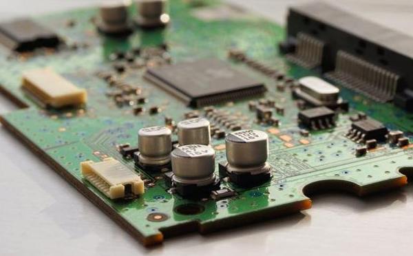
3. Inspection requirements of SMT patch processing products
In SMT patch processing, the electronic products after processing need to be inspected. What are the main points of inspection? Let's take a look:
1, printing process quality requirements
(1) The position of tin paste is in the middle, without obvious deviation, which can not affect paste and solder;
(2) printing tin paste is moderate, can be good paste, no less tin, tin paste too much;
③, tin pulp point forming good, should not even tin, uneven.
2, component mounting process quality requirements
(1) Components shall be mounted neatly, in the middle, without deviation and skew;
(2) The model and specification of the components in the mounting position should be correct; The components shall have no missing stickers and wrong stickers;
③, patch components are not allowed to have reverse paste;
(4) The installation of the patch device with polarity requirements shall be in accordance with the correct polarity mark;
⑤, components shall be mounted neatly, in the middle, without deviation and skew.
3, components soldering process requirements
①, FPC board surface should not affect the appearance of the solder paste and foreign bodies and markings;
(2) The adhesive position of components should not affect the appearance and solder rosin or flux and foreign matter;
(3) The tin point under the components is well formed, and there is no abnormal wire drawing or point drawing.
4. Technological requirements for the appearance of components
(1) The bottom of the board, the surface of the board, copper foil, line, through hole, etc., should have no cracks or cuts, no short circuit caused by bad cutting;
(2) The FPC board is parallel to the plane, and the board has no convex deformation;
(3) FPC board should not leak V/V bias phenomenon;
(4) There is no ambiguity, offset, reverse printing, bias, glint, etc.;
(5) The outer surface of the FPC board should be free from expansion and bubbling;
⑥, aperture size requirements meet the design requirements.


Достаточно загрузить файлы Gerber, BOM и проектные документы, и команда KINGFORD предоставит полное предложение в течение 24 часов.